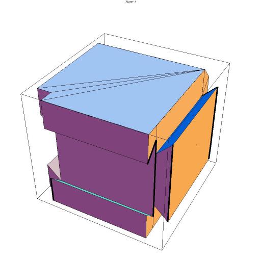
Figure 1 shows a single instance of a possible cell of cubic topology.
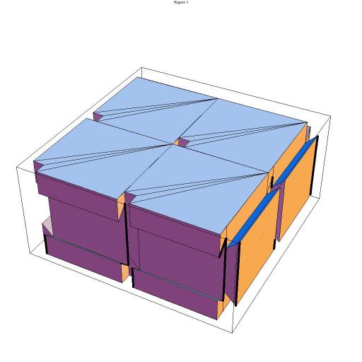
Figure 2 shows two rows of cubic elements with dovetail channels on four of their faces. The elements of each row are locked together by dovetail joints perpendicular to the sliding interface, but the two rows may slide relative to one another as units. Initiating a four-phase stepper sequence through the sets of magnetic elements in one row of cells will cause the row to exert force on the neighboring row and initiate sliding in a particular direction along the interface.
A cell may slide across the interface between rows by traversing the end of the row as shown in Figure 3.
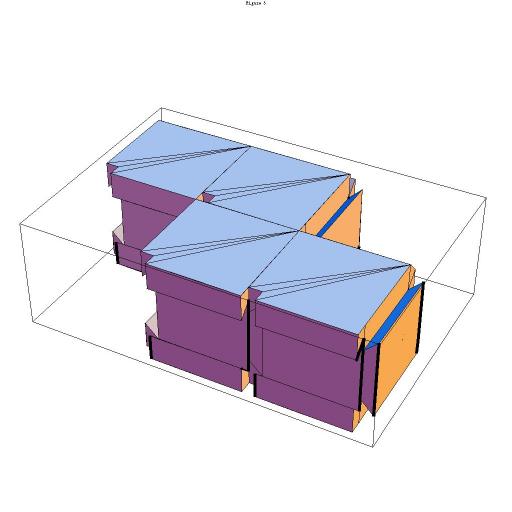
Figure 3 -- One Cubic Cell Traversing Two Rows.
It appears that the magnetic field constraints in a vanishingly small array of packed cells may be difficult to overcome, therefore it might be advantageous to revert to the model of an old cog railway. A two-phase NiTinol ratchet-type motor drive might be compact and easy to engineer. The most difficult problem to solve in this scenario might be thermal load, as NiTinol muscle wires require a heating-cooling cycle to operate.
Another, more attractive alternative is the piezo-electric "inch-worm" motor. The electrostatic problem is easier to deal with at small scale than the electromagnetic alternative. Piezo-electric motors also have very low electrical and thermal load. The following development will refer to piezo-electric motors in the design.
It seems reasonable to assume that electrical power to drive the cell can be transmitted through the sliding surfaces of the dovetail track. A scheme must be devised such that power can be transmitted efficiently from cell to cell throughout the entire structure while the cells are in motion. To guard against noise in electrical power due to sliding electrical contacts, it might be advantageous to specify that there should be a rechargeable electrical energy storage device in each cell to maintain clean power in a real-world environment.
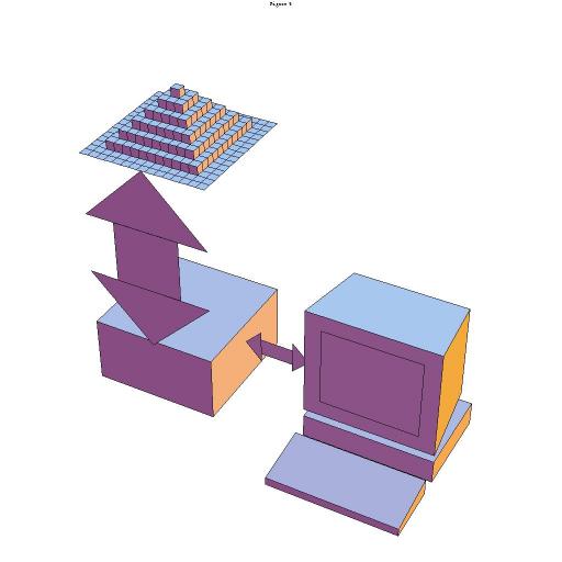
Figure 4 -- Global Structural Interface Schematic.
There will be mechanical and electrical constraints in the organization of cells in the dynamic sculpture in that cells distant from the base will be dependent upon cells nearer the base for their electrical power supply and mechanical support. Horizontal extensions out from the main bulk of the sculpture must be given a generally conical shape, after the shape of a branch growing from the trunk of a tree. The reason for this is to limit the mechanical strain on the motor cells nearer the trunk and to limit the electrical current per cross-sectional area flowing from the trunk to the cells at the extremities. The actual importance of this constraint will depend upon the strength and current-carrying capability of the cells as the design evolves.
It seems that a tactile detector can be a simple spring-loaded three-state switch. State zero is when the detector is in contact with nothing. State one is when the spring is depressed halfway; i.e., the pressure exerted by the outside on the cell is equal to that exerted back by the cell. State two is when the spring is fully depressed; i.e., the pressure exerted from outside is greater than that exerted by the cell.
The cubic design shown thus far is limited to two-dimensional sliding. A geometric design must be found which will allow both three-dimensional translation and rotation. Since this design is likely to determine many other aspects of the final design, the mechanical problem is probably the highest priority.
A polyhedral design strategy is attractive, because it allows for the possibility of perhaps as few as two mechanically distinct types of faces to be assembled to form each cell. The faces of a cell will be electrically distinct only to address the problems of power and data transmission. The dovetail joints can be modified to add mechanical "latches" which change the direction of travel in perpendicular directions.
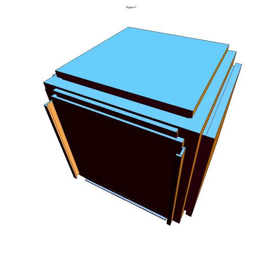
Figure 5 shows a cubic cell which has been modified to include movable latches in the design of the sliding joints. The faces to the top and right are static "male" joining members, while the face at the lower left is a "female" joining surface with movable latches. The top and bottom pair of latches are shown retracted or open, while the left-and-right pair of latches are shown extended or closed. Latches in this configuration would allow for motion in the vertical direction at this face.
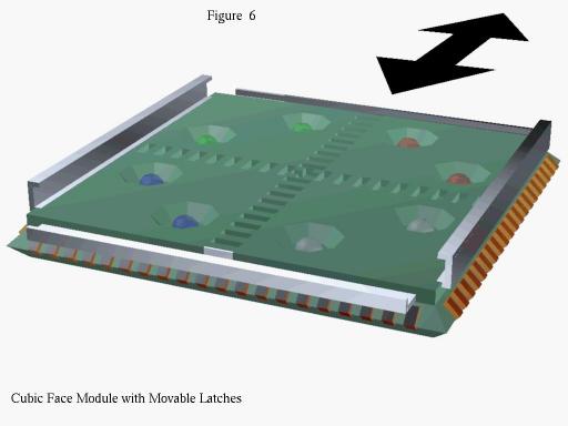
Figure 6 shows a single, modular face element of a cubic cell - in particular, the element of the "female" type with movable latches. Detail has been added in the form of electrodes - 20 along each edge - which will serve to join the faces together both electrically and mechanically to form a complete cubic cell. The design has been modified to bevel the edges of the cube such that the electrodes can be butted together and joined by soldering. It is proposed that cubic cells composed of modules of exactly two kinds can be mass-manufactured using the composite epoxy-glass, plated-through, multi-layer circuit construction technology.
Not shown in Figure 6 are the surface-mounted large-scale hybrid integrated circuits (LSI/HIC) which will be located on the interior of the cell, on the reverse side of the face.
The movable latches of the module in Figure 6 are in the state to allow motion along the direction indicated by the arrow. Closing the front-back pair of latches and opening the left-right pair of latches would allow motion in the left-right direction, perpendicular to the arrow, but remaining in the plane of the face. Motion perpendicular to the plane of the face is even allowed, by opening all latches at once. It is therefore now up to software and fail-safe design to hold the cellular structure together.
Figure 6 also shows recessed light-emitting diodes and solid-state photodetectors of red, green, blue and infrared spectral discrimination, and a notched "track" which serves to engage piezo-electric inch-worm motor elements installed in the "male" joining member of a cubic cell, shown in Figure 7.
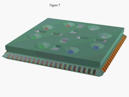
Figure 7 also shows edge-mounted electrodes, recessed photo-emitters, -detectors, the slots into which the latches of the female face engage and four pairs of piezo-electric inch-worm motor elements, shown retracted in the figure.
The base plane supporting and interface structure for the large-scale sculpture can be constructed from the identical "male" face modules shown in Figure 7. The additional design required is the large-scale, printed substrate with square sites into which the face modules are installed for multiplexed electrical interface and to establish the cellular lattice spacing. This base unit is shown in Figure 10.
The base plane calls for a hierarchical design. A single base module is proposed to consist of sixteen cell-face mounting sites with raised electrodes to allow clearance for the surface-mounted LSI/HICs on the reverse sides. The electrical scheme for the base plane should allow for automatic detection of whether a cell is installed at a site or not, to permit a design which breaks from the strict, rectangular lattice. The addressing circuitry should establish where addressable lattice sites exist and the paths a cell travels to get from one site on the boundary of the base to the next.
The sixteen-cell base module in turn connects mechanically and electrically to a larger substrate which serves higher-level address multiplexing. If each higher-level base module holds 16 base modules, then it will hold a total of 256 cells. Perhaps at this level, there is a common interface at each module, one of which can interface to the host computer.
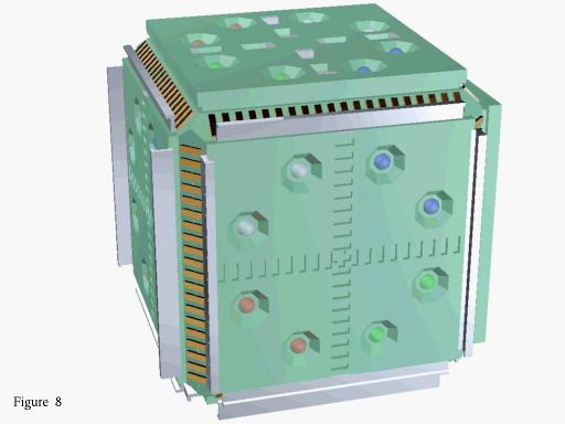
Figure 8 -- One Complete Cell with Movable Latches.
The placement of the light emitters and detectors on each face of a cell will be such that emitters will be aligned with the detectors of corresponding spectral band on the face of its neighboring cell. The mechanical tolerances in the construction of the base is fairly critical, because it establishes the cubic lattice. Likewise, subtle features should be present in the design of cell tracks to allow for smooth travel over the joints between cells with a reasonable tolerance for misalignment.
The geometry of the "track" slots in the female face and the range of motion of the motor elements are critical with respect to each other and to the spacing of faces along a row of cells. The slots are shown unrealistically large in Figure 6 for clarity. The range of motion of the motor elements is probably such that the slots will need to be much closer together and more numerous. The slots are also shown rectangular in all cross sections. This is also probably unrealistic, but would be an advantage in allowing maximal transverse motor force with a minimum of force on the latches, perpendicular to the face.
The spacing of the motor elements in any of the two directions in the plane of a face is such that at least two of the elements will always be engaged in the track as the cell in passing over the joint between two neighboring cells at that face. This situation is shown in Figure 9.
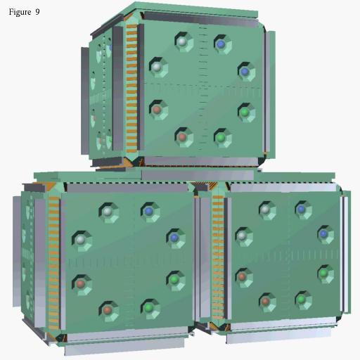
Figure 9 -- Two Cells Traversed by One.
The latch design is such that when cells are aligned, all four latches on a face may close, holding the structure rigid without expending any energy in the motors. If the latch movement can be mechanically two-state, then energy need only be expended in changing state open or closed.
The preceding design, with movable latches, provides a flexible motion in three dimensions, including the possibility to separate sections of the sculpture from itself in a fluid manner. Rotation is not yet possible, but it is the opinion of the artist that the capability developed thus far is sufficiently powerful to warrant building a prototype.
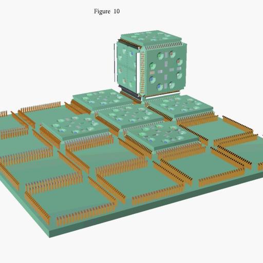 Figure 10 -- One Cubic Cell on Base Plane.
3-D Kinetic cellular Automaton -- Copyright 1995 Stewart Dickson