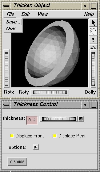
This is a program, written using Open Inventor to be used for creating dimensional thickness on a single-sided (open) polygon surface mesh.
The program reads and writes Open Inventor format geometrical obejct description files.
The program has an interactive and a non-interactive, batchable mode.
When the -gui option is specified on the command line (and outfile is omitted), the program launches an Open Inventor SoXtExaminerViewer containing the thickened version of the specified Open Inventor infile. SoXtExaminerViewer allows the user to interactively zoom and tumble the object under control of the mouse. The user may also change the style of rendering of the displayed object.

Along with the SoXtExaminerViewer is displayed a UI window marked Thickness Control. This window contains a Thumbwheel and TextField to allow the user to adjust the thickness displacement applied to the thickened version of the input surface.
When the -gui option is used, the user is expected to use the File->Save... menu in the user interface to save the thickened object, when the thickness is adjusted to the desired value.

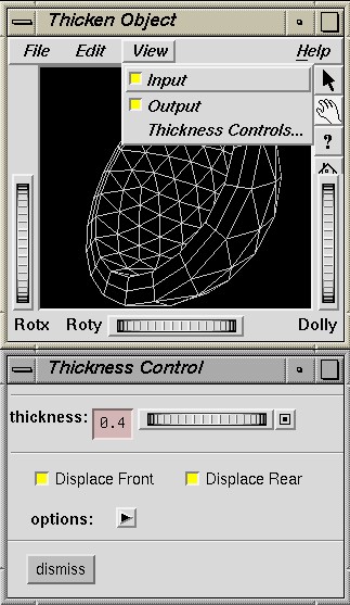
The thicken user interface also contains controls to turn off and on the original infile geometry and the thickened version of the same. The two may be viewed simultaneously when rendered in wireframe or hidden line mode. The display state does not affect the output written to outfile. Only the thickened object will be written to the output at the current thickness, no matter what combination of objects are displayed.
The thicken View pulldown menu also contains an item button to re-display Thickness Controls... after they have been dismissed.

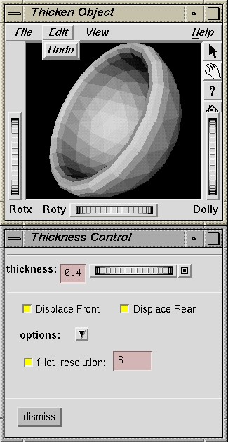
Thickness Control Options, in addition to Displace Front/Rear, include an option to fillet the stitched edge between the front and rear surfaces with a rounded edge of variable polygon resolution.
The Thickness Control options ArrowButton is used to hide the fillet options form and collapse the user interface to save space.
Thicken assumes that the given infile is a topologically continuous polygon mesh. Currently, only Open Inventor IndexedFaceSet and QuadMesh nodes are recognized in the input. And neighboring polygons sharing a common edge must reference the same, single pair of vertices defining that edge.
Open Inventor FaceSet nodes do not work, because each face references a unique set of vertices and common edges are undefined because they contain redundant vertices. 'STL' files have a similar problem, intrinsic in their geometry representation format.
Topologically continuous polygon meshes can be obtained by welding the input file to remove the redundant vertices on common polygon edges and to induce polygons to reference the same vertices on each side of the edge.
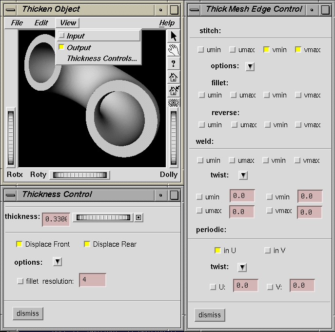
If the input Open Inventor infile contains a QuadMesh node, then an additional user interface is launched, titled "Thick Mesh Edge Control", to provide further control over aspects of the surface unique to the QuadMesh node.

The QuadMesh node is a strictly-ordered rectangular array of quadrilaterals. It is determined solely by an also rectangular array of three-dimensional coordinates in strict row-major order. With the inherent order implied in a surface such as this, it can be treated as parametric surface. The vertices are ordered sequentially in rows in the iso-V direction and columns in the iso-U direction.
The first row of vertices is denoted VMIN, the last row is denoted VMAX. The column starting with the first vertex (V * verticesPerRow) is denoted UMIN and the column starting with the last vertex in the first row (V * (verticesPerRow-1)) is denoted UMAX.
The default operation of the thicken program is to construct a quadrilateral from each edge of the front surface which bounds only one face, to the corresponding edge in the rear surface. This is the criterion which determines the open boundary of the surface.
In a QuadMesh, we can separately identify the four continuous edges bounding the surface by their respective parametric addresses, UMIN, UMAX, VMIN and VMAX. And we can control the behavior by which the front surface is joined to the rear surface separately on each edge.
In a topological surface, such as a torus, the surface is actually joined to itself and is said to be periodic. The thicken program user interface provides the means to suppress construction of polygons internal to the thickened torus at the UMIN/UMAX boundaries (in the above example), and to weld the front and rear surfaces to themselves at the UMIN/UMAX edges.
There are further options to handle surfaces (such as non-orienteable ones, including the Klein bottle) which close themselves with a twist. The twist and options ArrowButtons hide the associated options forms and allow the user interface to collapse to save room.